Universal Tamping Machines
S7 PLS 16 4.0
The Revolution for Highest Tamping Quality

The Revolution for Highest Tamping Quality

Huge Reduction On Wear

INTEGRATION OF 3RD POINT LIFTING INTO MAIN LIFTING AND LINING UNIT

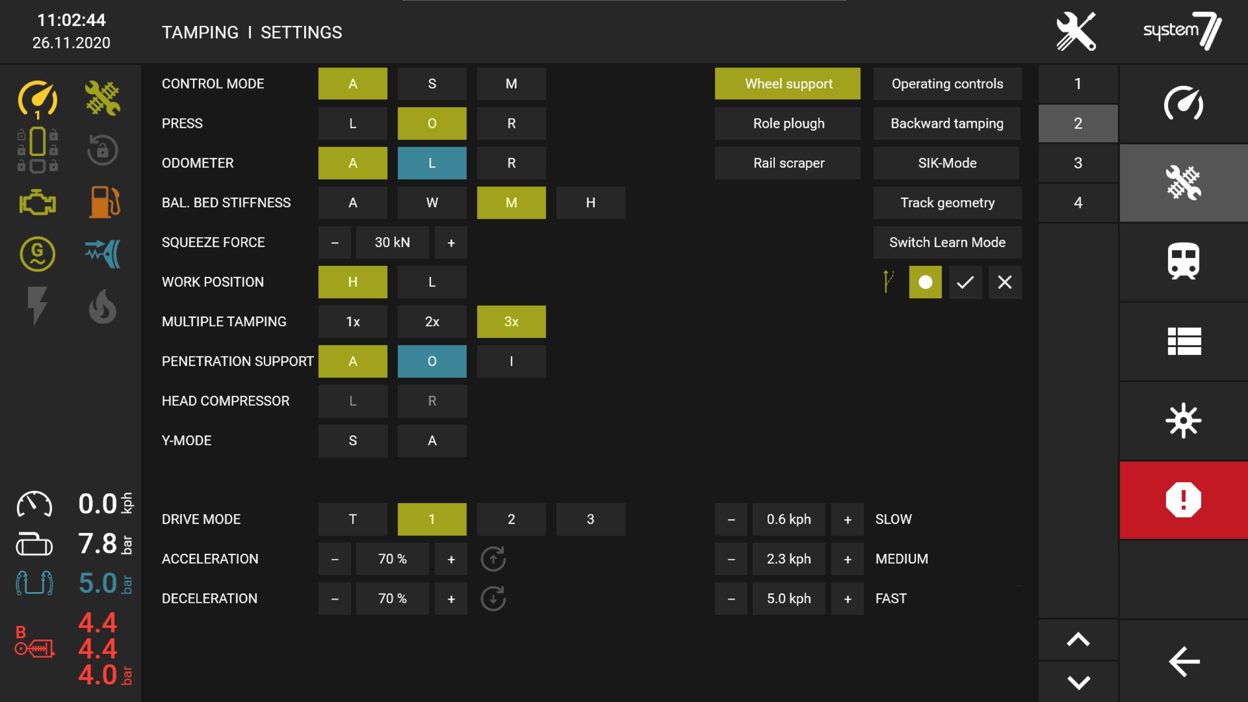
S7 AUTOMATIC TAMPING FOR OPTIMUM COMPACTION

REMARKABLE NOISE AND DUST REDUCTION
BALLAST BED ANALYSIS WITH SYSTEM7 INFRASTRUCTURE MANAGEMENT WEB PLATFORM "INFRAME"

BALLAST BED Report
The basis for the ballast bed report, which is created on the System7 tamping machines immediately after the work, is formed by measurement data from tamping unit sensors, parameters from the track geometry acceptance recorder APPRec and the control computer CEO++.
This data is automatically analysed using machine learning and summarised and output in the ballast bed report. In addition to the graphical representation of the ballast bed properties and the compaction achieved, long-wave longitudinal faults before and after tamping are also drawn. A written summary assesses the ballast bed quality and points out any single faults in the track
Click to see the pictures in details
AUTOMATED INTUITIVE TAMPING OPERATIONt
The basis for the ballast bed report, which is created on the System7 tamping machines immediately after the work, is formed by measurement data from tamping unit sensors, parameters from the track geometry acceptance recorder APPRec and the control computer CEO++.
This data is automatically analysed using machine learning and summarised and output in the ballast bed report. In addition to the graphical representation of the ballast bed properties and the compaction achieved, long-wave longitudinal faults before and after tamping are also drawn. A written summary assesses the ballast bed quality and points out any single faults in the track


Switch Engineer
Lifting Tool Assistant
Switch learning mode assistance system
Open the gallery by clicking on the picture.
OPTICAL MEASURING SYSTEM
Conventional measuring and control systems for track-maintenance machines are usually constructed from steel chords, tensioning devices, measuring sensors for height and direction and physical pendulums. Disadvantages of this system are required clearances for the chords on the machine, external forces on the chords cause track position errors, vibrating or damped chords cause inaccuracies, lack of chord tension or hooking of the chords interferes with the function, steel chords can break and exhibit drift. Physical pendulums are sensitive to vibrations and react incorrectly to accelerations.
The optical measuring system from System7 avoids the disadvantages of mechanical steel chords such as sagging, hooking, vibrating, breaking off, conflicts with obstacles in the machine, damping of the system, temperature drifts, shifting of the zero points, dependencies on vibrations, etc.

THE SYSTEM7 PRECISION MACHINE MEASUREMENT SYSTEM
- The aperture of the camera is closed wide. This makes the system independent of stray light and daylight.
- The function of the system is independent of weather conditions such as fog, rain or snow.
- Huge reduction of life cycle costs and easy maintenance compared to conventional tamping technology
The camera system detects the LED patterns by means of image recognition processes and recognizes them clearly and robustly. The system is fault-tolerant. The system continuously checks itself.
The measuring system is available in tropical and polar versions.

ABSOLUTE POSITIONING SYSTEM INSPIRED BY AVIATION
